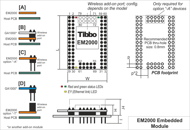
Mechanical Dimensions
Notes:
Standard EM2000 devices do not have a wireless add-on connector (a.k.a., "SPI port") and the "landing" PCB area for the connector is left empty (cross-section A). Compatible wireless add-on modules (such as the WA2000 Wi-Fi add-on module) can optionally be soldered into the connector pads (cross-section B).
Option "-A" EM2000 devices feature a 10-pin wireless add-on header (cross-section C). The pins on this header are identical to all other pins of the EM2000 and face the host PCB. This way, the wireless add-on port of the EM2000 can be connected to some other circuitry on the host PCB. For example, instead of mounting onto the EM2000, the WA2000 add-on can be mounted directly onto the host PCB. An option "-A" EM2000 module is then required to facilitate the connection between the EM2000 and the wireless add-on.
Finally, option "-T" devices have a female wireless add-on port connector, which the WA2000 can be plugged into. EM2000 modules of the "-T" variety (cross-section D) are intended for convenient testing of wireless modules and are not recommended for use in production devices.
|
L |
Max. |
38.4 |
Module length |
|
W |
Max. |
28.4 |
Module width |
|
H |
Max. |
5.5 |
Module height |
|
H' |
Max. |
11.0 |
Module height with the WA2000 module soldered into the EM2000 module |
|
h |
Max. |
4 |
Additional height added by the supercapacitor ("-S" option devices only) |
|
I |
Min. |
6.0 |
Lead length |
|
p |
Aver. |
2.54 |
Pin pitch |
Dimensions are for reference only. Tibbo assumes no responsibility for any errors in this manual, and does not make any commitment to update the information contained herein.