Multi-Channel RS232 Port and Expansion Connector
The EM1206 module has four serial ports (four pairs of RX and TX lines). Each of those lines can also be used as general-purpose I/O (GPIO). Hence, each line can serve as a CTS, RTS, DSR, or DTR line; or play another role that is unrelated to the function of a serial port.
The I/O lines of the EM1206 are bi-directional: each line can be programmed to work as an output or input line. However, on the RS232 port of the EM1206EV, each line has a fixed direction defined by the RS232 transceiver IC. The IC used on the EM1206EV implements three outputs and four inputs. Therefore, only seven I/O lines of the EM1206 are connected to the RS232 port of the EM1206EV.
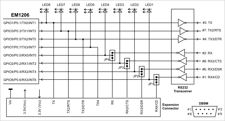
Out of these seven lines, each of the three outputs can be used as a TX line of a serial port or as a control output, such as RTS or DTR. Each of the four input lines can be used as an RX line of a serial port or as a control input, such as CTS, DSR, or CD. As such, the RS232 port of the EM1206EV offers 3.5 serial "channels." We say "3.5 channels" and not "four channels" because one channel will only have an RX line and no TX line (remember, there are four inputs, but only three outputs).
Note that all four inputs of the serial port are connected to the EM1206 through jumpers. Jumpers are necessary to select between the RS232 port inputs and expansion connector terminals. Putting a jumper "up" selects an input from the RS232 transceiver; putting a jumper "down" selects an expansion connector line.
All eight lines are available on the expansion connector as TTL signals. When the expansion connector is used, any of these eight lines can be used as an input or output.
You can conveniently see the state of I/O lines on a bank of yellow LEDs. An LED is ON when its corresponding TTL line is HIGH. Note that the RS232 transceiver IC inverts the signal on each line. For example, if the GPIO1/P0.1/TX/INT1 pin of the EM1206 is HIGH, then the TX pin on the DB9M collector is LOW.
For more information on serial ports and the I/O lines of the EM1206, see the ser. object and io. object documentation.
The serial-over-IP application offered by Tibbo defines 15 "mapping options," or ways to utilize the available I/O lines. These are presented in the table below:
|
Mapping option |
Available signals |
DB9M connector pins |
Missing line |
||||||
|
#2 |
#3 |
#8 |
#7 |
#6 |
#4 |
#1 |
|||
|
Option 0 |
RX/TX/CTS/RTS/DSR/DTR |
RX |
TX |
CTS |
RTS |
DSR |
DTR |
--- |
--- |
|
Option 1 |
RX/TX/CTS/RTS/DSR/DTR + RX/tx |
RX |
TX |
CTS |
RTS |
DSR |
DTR |
RX4 |
tx4 |
|
Option 2 |
RX/TX/CTS/RTS + RX/TX + RX/tx |
RX |
TX |
CTS |
RTS |
RX3 |
TX3 |
RX4 |
tx4 |
|
Option 3 |
RX/TX/CTS/RTS + RX/TX/CTS/rts |
RX |
TX |
CTS |
RTS |
RX3 |
TX3 |
CTS3 |
rts3 |
|
Option 4 |
RX/TX/CTS/RTS + RX/TX/DSR/dtr |
RX |
TX |
CTS |
RTS |
RX3 |
TX3 |
DSR3 |
dtr3 |
|
Option 5 |
RX/TX/DSR/DTR + RX/TX + RX/tx |
RX |
TX |
RX2 |
TX2 |
DSR |
DTR |
RX4 |
tx4 |
|
Option 6 |
RX/TX/DSR/DTR + RX/TX/CTS/rts |
RX |
TX |
RX2 |
TX2 |
DSR |
DTR |
CTS2 |
rts2 |
|
Option 7 |
RX/TX/DSR/DTR + RX/TX/DSR/dtr |
RX |
TX |
RX2 |
TX2 |
DSR |
DTR |
DSR2 |
dtr2 |
|
Option 8 |
RX/TX + RX/TX + RX/TX + RX/tx |
RX |
TX |
RX2 |
TX2 |
RX3 |
TX3 |
RX4 |
tx4 |
|
Option 9 |
RX/TX/CTS/rts + RX/TX + RX/TX |
RX |
TX |
RX2 |
TX2 |
RX3 |
TX3 |
CTS |
rts |
|
Option 10 |
RX/TX/DSR/dtr + RX/TX + RX/TX |
RX |
TX |
RX2 |
TX2 |
RX3 |
TX3 |
DSR |
dtr |
|
Option 11 |
RX/TX/CTS/RTS + RX/tx/CTS/RTS |
RX |
TX |
CTS |
RTS |
CTS4 |
RTS4 |
RX4 |
tx4 |
|
Option 12 |
RX/TX/CTS/RTS + RX/tx/DSR/DTR |
RX |
TX |
CTS |
RTS |
DSR4 |
DTR4 |
RX4 |
tx4 |
|
Option 13 |
RX/TX/DSR/DTR + RX/tx/CTS/RTS |
RX |
TX |
CTS4 |
RTS4 |
DSR |
DTR |
RX4 |
tx4 |
|
Option 14 |
RX/TX/DSR/DTR + RX/tx/DSR/DTR |
RX |
TX |
DSR4 |
DTR4 |
DSR |
DTR |
RX4 |
tx4 |
|
Mapping option |
Available signals |
RX |
TX |
RX2/CTS |
TX2/RTS |
RX3/DSR |
TX3/DTR |
RX4 |
TX4 |
|
Terminals of the expansion connector (as marked on the EM1206EV) |
|||||||||
The "Available signals" column shows a particular combination of I/O lines for each option. For example, option 0 defines the standard serial port arrangement with RX, TX, CTS, RTS, DSR, and DTR lines. Option 2 gives you one channel with RX, TX, CTS, and RTS lines, one more channel with just RX and TX lines, and yet another channel with a single RX line. The TX line is "missing" because, once again, there are only three outputs available. This is why this line is shown in gray and lowercase (tx). This line, of course, is present and available on the expansion connector.