LED Lines
Pin Functions and Descriptions
|
Pin Number |
Signal Name |
Direction |
Description |
|
#4 |
L1 (ER) |
Output |
LED output 1, Red Ethernet status LED |
|
#5 |
L2 (EG) |
Output |
LED output 2, Green Ethernet status LED |
|
#6 |
L3 (SG) |
Output |
LED output 3, Green status LED |
|
#7 |
L4 (SR) |
Output |
LED output 4, Red status LED, Watchdog reset line |
Line functions defined by the Application Firmware are shown in blue.
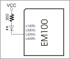
The EM100 has four LED control lines. All lines share the same internal structure, and LEDs should be connected to these lines as shown in the schematic diagram below. The maximum load for each line is 10mA.

LED Control Line Functions
The firmware of the EM100 assigns specific functions to these LED control lines. These functions are shown in blue in the table at the top of this topic.
- ER and EG Lines:
These lines reflect the status of the Ethernet port.
- The EG LED is normally ON and is temporarily turned off whenever the EM100 receives a network packet.
- The ER LED is normally OFF and is temporarily turned on whenever a data collision is detected on the Ethernet.
Additionally, the ER line serves as a watchdog reset line. Very short (<10µs) pulses are generated on this line at a rate of about 100Hz. When connected to the watchdog reset pin of an external reset/watchdog IC, the ER line keeps the watchdog "in check," preventing it from resetting the EM100. These watchdog reset pulses do not interfere with the main function of the ER line (i.e., indicating the status of the Ethernet port) as the pulses are so short that they are not visible on the LED connected to the ER line.
Strictly speaking, the ER and EG lines are under firmware control. Their behavior is described here because they are typically used as standard Ethernet status LEDs (similar to those found next to the RJ45 connector on PC network cards).
- SR and SG Lines:
The SR and SG LEDs display various status information depending on the firmware currently running.
Follow the links below to learn more about the behavior of these LEDs under different conditions:
