General-Purpose I/O Lines
The EM1001 has 54 general-purpose I/O (GPIO) lines (GPIO0 ~ GPIO53). All lines are 3.3V, CMOS, and 5V-tolerant. The maximum load current for each I/O line is 10mA. Forty-nine of these lines are always available. The remaining five lines are located on the wireless add-on connector and can be used if no wireless add-on module is installed.
Forty of the I/O lines are combined into five 8-bit ports.
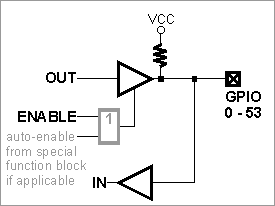
The simplified structure for one I/O line is shown in the circuit diagram below. Each line has an independent output buffer control. When the EM1001 powers up, all I/O lines have their output buffers tri-stated (in other words, all I/O lines are configured as inputs). You need to explicitly enable the output buffer of a certain I/O line if you want it to work as an output.
Many I/O lines of the EM1001 also serve as inputs or outputs of special function modules, such as serial ports. The majority of those lines need to be correctly configured as inputs or outputs — this won't happen automatically. Several lines — such as TX and RX lines of the serial port when in the UART mode — are configured as outputs and inputs automatically when the serial port (or some other hardware block) is enabled. For details, see the EM1000 programming platform.
Each I/O line has a weak pull-up resistor that prevents the line from floating when the output buffer is tri-stated.
I/O line control is described in detail in the documentation for the io. object.