Power, Reset, PLL Control, and Mode Selection Lines
The EM1000 should be powered from a stabilized DC power supply with a nominal output voltage of 3.3V (±5% tolerance). This power should be applied to pin #60. The "-A" modification of the EM1000 has a second VCC pin (#72). To prevent "current loops," only use either pin #60 or pin #72 to supply power to the device.
The EM1000's current consumption is approximately 230mA (PLL on, 100BaseT mode). This does not include the power consumption of any installed wireless add-on module, such as the WA2000. The slave module, depending on its type, can add significantly to the power consumed by the EM1000. Therefore, providing an adequate power supply is very important — a poorly built circuit may affect EM1000 operation. We recommend that you use a switching power supply. One (but not the only) example of such circuit is shown below.
Please, do not forget that the VCCB pin should not be left unconnected (see Real-Time Counter).
A proper external reset is not required. The EM1000 has a reliable power-on reset circuit with brown-out detection. Optionally, you can connect a reset button or some other reset-generating circuit to the RST pin. This will allow you to generate "external" resets. The RST line has active HIGH polarity. If you are not using the RST pin, you can leave it unconnected.
The main clock frequency of the EM1000 is generated by the 11.0592MHz crystal connected to the onboard PLL circuit. When the PLL is off, the EM1000 is clocked at 11.0592MHz. When the PLL is on, the main clock is eight times higher at 88.4736MHz. Naturally, with PLL turned on the EM1000 works eight times faster and consumes more current (230mA with PLL on against 110mA with PLL off). The main clock frequency also affects the baudrates of serial ports when in the UART mode, as well as the frequency produced by the square wave generator.
The PLL cannot be switched off and on while the EM1000 is running. This is because when the PLL mode changes its output, it needs some time to stabilize. For this reason, the PLL mode of the EM1000 can only be changed on reset. A special internal delay circuit will hold the EM1000 in reset while the PLL frequency stabilizes.
The state of the PM pin at power-on or external reset (i.e., a reset pulse on the RST line) defines whether the EM1000 will run with PLL on or off. To have the PLL on, leave the PM pin unconnected. To disable PLL and run at a lower clock frequency, ground the PM pin.
Your Tibbo BASIC/C application can also change the PLL mode programmatically. The Tibbo BASIC/C application can check the current PLL mode through the sys. object. If the PLL mode needs to be changed, the application can set a new mode and then perform an internal reset (again, through the sys. object). The internal reset is identical to the power-on or external reset with one difference: the PLL mode is set based not on the PM pin, but on the PLL mode requested by the application prior to the reset.
The function of the MD line is described in Setup (MD) Button (Line).
Power Supply Circuit
Many power supply circuits will work well. The one shown below is used by Tibbo. The circuit can handle input voltages in the 9V~24V range.
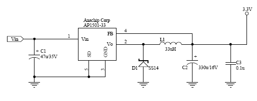
Notes:
- U1 (AP1501-33) is a popular power IC manufactured by Anachip (now Diodes Inc. — www.diodes.com).
- C1 and C2 capacitors: Do not use SMD capacitors — use regular through-hole aluminum capacitors. This really helps reduce noise produced by the power supply.
- This is an analog circuit, so layout matters. Apply reasonable "good layout" effort.
 Ideally, you should use an oscilloscope to see what sort of "square wave" the power supply generates, both at low and high input voltages, as well as light and heavy loads. There are no recipes here — just try and see what works for your circuit.