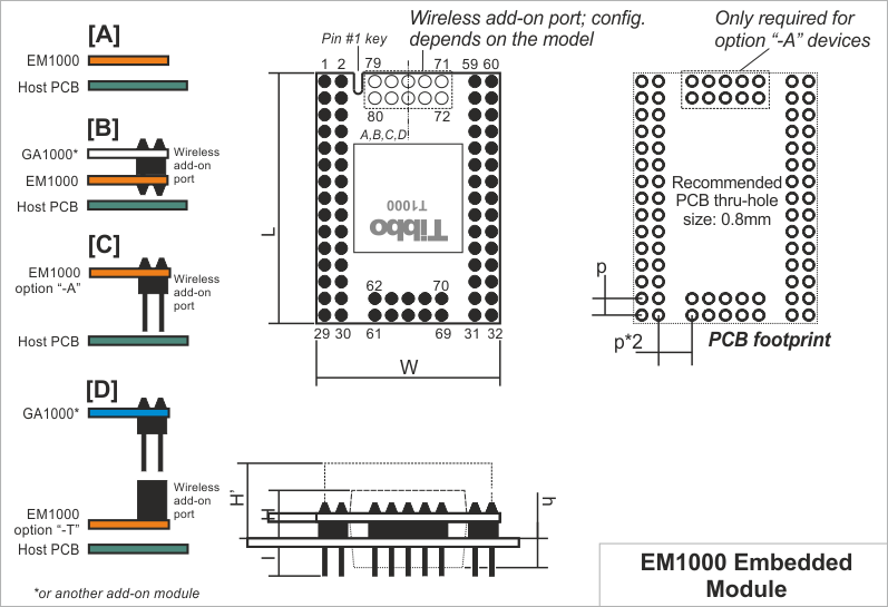
Mechanical Dimensions

Notes:
Standard EM1000 devices do not have a wireless add-on connector (a.k.a., "SPI port") and the "landing" PCB area for the connector is left empty (cross-section A). Compatible wireless add-on modules (such as the WA2000) can optionally be soldered into the connector pads (cross-section B).
Option "-A" EM1000 devices feature a 10-pin wireless add-on header (cross-section C). The pins on this header are identical to all other pins of the EM1000 and face the host PCB. This way the wireless add-on port of the EM1000 can be connected to some other circuitry on the host PCB. For example, instead of mounting onto the EM1000, the WA2000 can be mounted directly onto the host PCB. Option "-A" modules are then required to facilitate the connection between the EM1000 and the WA2000.
Finally, option "-T" devices have a female wireless add-on port connector, which the WA2000 can be plugged into. EM1000 modules of "-T" variety (cross-section D) are intended for convenient testing of the WA2000 and are not recommended for use in production devices.
|
L |
Max. |
38.4 |
Module length |
|
W |
Max. |
28.4 |
Module width |
|
H |
Max. |
5.5 |
Module height |
|
H' |
Max. |
11.0 |
Module height with the WA2000 module soldered into the EM1000 module |
|
h |
Max. |
4 |
Additional height added by the supercapacitor ("-S" option devices only) |
|
I |
Min. |
6.0 |
Lead length |
|
p |
Aver. |
2.54 |
Pin pitch |
Dimensions are for reference only. Tibbo assumes no responsibility for any errors in this manual, and does not make any commitment to update the information contained herein.
