Ordering Info and Specifications
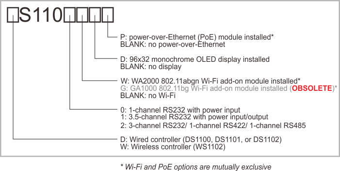
Device numbering scheme for DS/WS110x devices is as follows:
Visit our online store for an up-to-date list of accessories offered with DS/WS110x devices.
Examples of Valid Model Numbers
|
Model number |
Description |
|
WS1102 |
Wireless controller with 802.11a/b/g/n Wi-Fi and BLE4.2 interfaces, universal RS232/422/485 serial port |
|
DS1101WD |
Wired controller with Ethernet port, universal 3.5-channel RS232 port, 802.11a/b/g/n Wi-Fi add-on, OLED display |
|
DS1102P |
Wired controller with Ethernet port, universal 3-channel RS232/422/485 serial port, Power over Ethernet (PoE) module |
Hardware Specifications
|
DS1100 |
DS1101 |
DS1102 |
WS1102 |
|
|
Device color |
 |
 |
 |
 |
|
Ethernet port |
10/100BaseT Ethernet, Auto-MDIX, debugging over Ethernet |
No |
||
|
Wi-Fi |
No |
Built-in 802.11a/b/g/n interface with optional auto-connect, wireless debugging, TLS1.2 encryption |
||
|
BLE |
No |
BLE4.2 |
||
|
Serial port |
RS232 port on a DB9M connector |
RS232/422/485 port on a DB9M connector |
||
|
Serial port channels |
1 |
3.5 |
|
1 |
|
Serial port lines |
TX, RX, RTS, CTS, DTR, DSR |
TX, RX, RTS, CTS, DTR, DSR, DCD |
|
|
|
Max. baudrate |
Up to 115,200bps |
Up to 460,800bps |
Up to 921,600bps |
|
|
Flow / direction control |
Optional RTS/CTS flow control |
|
||
|
Parity modes |
None/even/odd/mark/space parity |
|||
|
Bits/character |
7/8 bits/character |
|||
|
Power input/output on DB9 |
"12V" power input on pin 9 of DB9 |
"12V" power input and output on pin 9 of DB9 (software-controllable) |
No |
|
|
Flash memory |
512KB for firmware and application storage. No flash disk functionality. |
1,024KB for firmware, application and data (flash disk) |
|
|
|
EEPROM |
200 bytes, 180 bytes are available to store application data.(3) |
2,048 bytes, 2,020 bytes are available to store application data.(3) |
||
|
LEDs |
|
|
|
|
|
PoE |
Optional(1) |
No |
||
|
Buzzer |
No |
Yes |
||
|
Processor |
T2000 |
T1000 |
Tibbo Wi-Fi/BLE SoC |
|
|
Operating frequency and PLL |
80MHz |
88MHz, software-controlled PLL |
192MHz |
|
|
Firmware upgrades |
Through the serial port or network (including cold upgrades through the network) |
Through the serial port or network (no cold upgrades through the network) |
Through the serial port, Wi-Fi, or BLE (cold upgrades supported for all three interfaces) |
|
|
Supply voltage |
12VDC nominal (min. 9V, max. 18V)(4) |
|||
|
Current consumption |
~100mA @12VDC with spikes of up to 120mA |
|
~90mA @12VDC with spikes of up to 100mA |
|
|
Operating temperature range |
–5°C to +70°C |
–40°C to +85°C(4)(5) |
||
|
Operating relative humidity |
10% ~90% |
|||
|
Mechanical dimensions |
90x48x25mm |
|||
|
Carton dimensions |
137x99x70mm |
|||
- The Wi-Fi and PoE options are mutually exclusive.
- The DTR and DSR lines are not available if serial debugging is enabled.
- Typical write endurance is about 1,000,000 write cycles per EEPROM sector. See Prolonging and Estimating EEPROM Life.
- The WS1102 is compliant with the IEC/EN 62368-1 safety standard in the –40°C to +85°C range. To maintain this compliance in the field, use an external DC power source outputting 0.5A @ 9VDC~18VDC (less than 15W) that is also IEC/EN 62368-1 certified and can operate in the –40°C to +85°C range.
- Tested according to procedures I, II, and III of MIL-STD-810H Method 501.7 and MIL-STD-810H Method 502.7.
All specifications are subject to change without notice and are for reference only. Tibbo assumes no responsibility for any errors in this manual, and does not make any commitment to update the information contained herein.
Think the above table should contain additional data? Do not just assume that you know the answer — talk to Tibbo! Remember that the ultimate responsibility for all decisions you make regarding the use and the mode of use of Tibbo products lies with you, our customer.