WS1102
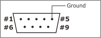
The WS1102 features a multimode RS232/422/485 port. Physically, the port is implemented as a single DB9M connector.
Note: See Definition of RS422 and RS485 Modes for information on how these modes are implemented on the WS1102.
Port Pin Assignment
In the RS232 mode, the serial port of the WS1102 has three output and three input lines. In the RS422 mode, you get two output and two input line pairs. The RS485 mode offers one output line pair and one input line pair. These are not independent — they operate in the half-duplex mode.
The serial port of the WS1102 is controlled via the ser. object.
|
RS232 |
RS422(3) |
RS485(3) |
|
|
#1 |
<No connection> |
RTS– (output) |
<No connection> |
|
#2 |
RX (input) |
RX– (input) |
RX– (input) |
|
#3 |
TX (output) |
TX+ (output) |
TX+ (output) |
|
#4 |
DTR (output)(1) |
TX– (output) |
TX– (output) |
|
#5 |
Ground |
Ground |
Ground |
|
#6 |
DSR (input)(2) |
RX+ (input) |
RX+ (input) |
|
#7 |
RTS (output) |
RTS+ (output) |
<No connection> |
|
#8 |
CTS (input) |
CTS+ (input) |
<No connection> |
|
#9 |
<No connection> |
CTS– (input) |
<No connection> |
- When serial debugging is enabled, this line ceases to work as the DTR line of the serial port and becomes the TX line of the debug serial port.
- When serial debugging is enabled, this line ceases to work as the DSR line of the serial port and becomes the RX line of the debug serial port.
- Serial debugging is not possible in these modes.
Selecting the Serial Port Mode
On the WS1102, the serial port mode is controlled via Microchip's MCP23008 I/O expander IC. The I²C interface of this IC is connected to GPIO5 and GPIO6 of the WS1102's CPU, as shown in the diagram below:

Use the ssi. object to communicate with the MCP23008. To select the desired serial port mode, set the state of the I/O expander's lines GP5 and GP6 as shown in the table below (these lines are not to be confused with GPIO5 and GPIO6, which are the CPU lines driving the I²C interface of the I/O expander). Both GP5 and GP6 should be configured as outputs.
|
Serial port mode |
GP5 |
GP6 |
|
RS232 |
HIGH |
LOW |
|
RS422 |
HIGH |
HIGH |
|
RS485 |
LOW |
HIGH |
Direction Control in the RS485 Mode
In the RS485 mode, which is half-duplex, the PL_IO_NUM_3_INT1 GPIO line acts as the direction control line. The line must be configured as an output.
|
Direction |
PL_IO_NUM_3_INT1 |
|
Output |
HIGH |
|
Input |
LOW |