Multi-Channel Serial Port
The DS1206N has four serial ports internally. The DS1206N-RS has an RS232 port with a DB9M connector, while "-TM" and "-TS" devices have a TTL serial port available through a TTL interface connector, which is a standard pin header with 2mm pitch.
The DS1206N-RS implements three outputs and four inputs. Each of the three outputs can be used as a TX line of a serial port or as a control output, such as RTS or DTR. Each of the four input lines can be used as an RX line of a serial port or as a control input, such as CTS or DSR.
With three outputs and four inputs, the DS1206N can be said to offer 3.5 serial "channels." We say "3.5 channels" and not "four channels" because one channel will only have an RX line and no TX line (remember, there are four inputs but only three outputs).
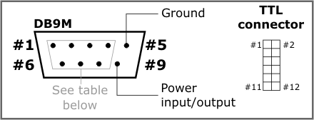
The TTL interface connector pin assignment is as follows:
|
Pin |
Name |
DS1206N-TM |
DS1206N-TS |
|
#1 |
3.3V |
Output to external device |
Input from external device |
|
#2 |
Power |
Power input/output |
Not used |
|
#3 |
GND |
Ground |
|
|
#4 |
RST |
Reset input, active LOW, use open collector driving circuit |
|
|
#5 |
Setup line input, active LOW, use open collector driving circuit |
||
|
#6-12 |
Lines of TTL serial port, see mapping table below |
||
For more information on controlling the serial ports and I/O lines of the DS1206N, see ser. object and io. object.
The serial-over-IP application offered by Tibbo defines 15 "mapping options" — or ways in which available I/O lines are utilized. These are presented in the table below:
|
Mapping option |
Available signals |
DB9M connector pins of the DS1206N-RS |
Missing line |
||||||
|
#2 |
#3 |
#8 |
#7 |
#6 |
#4 |
#1 |
|||
|
Option 0 |
RX/TX/CTS/RTS/DSR/DTR |
RX |
TX |
CTS |
RTS |
DSR |
DTR |
--- |
--- |
|
Option 1 |
RX/TX/CTS/RTS/DSR/DTR + RX/tx |
RX |
TX |
CTS |
RTS |
DSR |
DTR |
RX4 |
tx4 |
|
Option 2 |
RX/TX/CTS/RTS + RX/TX + RX/tx |
RX |
TX |
CTS |
RTS |
RX3 |
TX3 |
RX4 |
tx4 |
|
Option 3 |
RX/TX/CTS/RTS + RX/TX/CTS/rts |
RX |
TX |
CTS |
RTS |
RX3 |
TX3 |
CTS3 |
rts3 |
|
Option 4 |
RX/TX/CTS/RTS + RX/TX/DSR/dtr |
RX |
TX |
CTS |
RTS |
RX3 |
TX3 |
DSR3 |
dtr3 |
|
Option 5 |
RX/TX/DSR/DTR + RX/TX + RX/tx |
RX |
TX |
RX2 |
TX2 |
DSR |
DTR |
RX4 |
tx4 |
|
Option 6 |
RX/TX/DSR/DTR + RX/TX/CTS/rts |
RX |
TX |
RX2 |
TX2 |
DSR |
DTR |
CTS2 |
rts2 |
|
Option 7 |
RX/TX/DSR/DTR + RX/TX/DSR/dtr |
RX |
TX |
RX2 |
TX2 |
DSR |
DTR |
DSR2 |
dtr2 |
|
Option 8 |
RX/TX + RX/TX + RX/TX + RX/tx |
RX |
TX |
RX2 |
TX2 |
RX3 |
TX3 |
RX4 |
tx4 |
|
Option 9 |
RX/TX/CTS/rts + RX/TX + RX/TX |
RX |
TX |
RX2 |
TX2 |
RX3 |
TX3 |
CTS |
rts |
|
Option 10 |
RX/TX/DSR/dtr + RX/TX + RX/TX |
RX |
TX |
RX2 |
TX2 |
RX3 |
TX3 |
DSR |
dtr |
|
Option 11 |
RX/TX/CTS/RTS + RX/tx/CTS/RTS |
RX |
TX |
CTS |
RTS |
CTS4 |
RTS4 |
RX4 |
tx4 |
|
Option 12 |
RX/TX/CTS/RTS + RX/tx/DSR/DTR |
RX |
TX |
CTS |
RTS |
DSR4 |
DTR4 |
RX4 |
tx4 |
|
Option 13 |
RX/TX/DSR/DTR + RX/tx/CTS/RTS |
RX |
TX |
CTS4 |
RTS4 |
DSR |
DTR |
RX4 |
tx4 |
|
Option 14 |
RX/TX/DSR/DTR + RX/tx/DSR/DTR |
RX |
TX |
DSR4 |
DTR4 |
DSR |
DTR |
RX4 |
tx4 |
|
Mapping option |
Available signals |
#12 |
#11 |
#10 |
#9 |
#8 |
#7 |
#6 |
Missing line |
|
TTL connector pins of the DS1206N "-TM" and "-TS" |
|||||||||
The "Available signals" column shows a particular combination of I/O lines for each option. For example, option 0 defines the standard serial port arrangement with RX, TX, CTS, RTS, DSR, and DTR lines. Option 2 gives you one channel with RX, TX, CTS, and RTS lines, one more channel with just RX and TX lines, and yet another channel with a single RX line. The TX line is "missing" because, once again, there are only three outputs available. This is why this line is shown in gray and lowercase (tx).
Notice that on the DS1206N, pin 9 of the RS232 port can be used to power the DS1206N or to provide power to an attached serial device. See Power Arrangement for details.