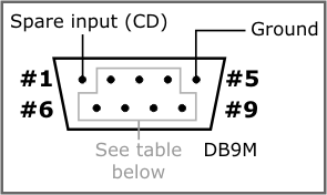
Multi-Channel RS232 Port
The DS1202 has four serial ports internally. The RS232 port implements three outputs, four inputs, and one "spare" input (CD). Each of the three outputs can be used as a TX line of a serial channel or as a control output, such as RTS or DTR. Input lines can be used as an RX line of a serial channel or as a control input, such as CTS or DSR. The spare input cannot work as an RX line. This input is not used by the serial-over-IP application supplied by Tibbo and will be largely omitted from further discussion. Your Tibbo BASIC/C application can always use this extra input if you require it.
With three outputs and four inputs, the DS1202 can be said to offer 3.5 serial "channels". We say "3.5 channels" and not "four channels" because one channel will only have RX line and no TX line (remember, there are four inputs but only three outputs).
|
Mapping option |
Available signals |
DB9M connector pins |
Missing line |
||||||
|
#2 |
#3 |
#8 |
#7 |
#6 |
#4 |
#9 |
|||
|
Option 0 |
RX/TX/CTS/RTS/DSR/DTR |
RX |
TX |
CTS |
RTS |
DSR |
DTR |
--- |
--- |
|
Option 1 |
RX/TX/CTS/RTS/DSR/DTR + RX/tx |
RX |
TX |
CTS |
RTS |
DSR |
DTR |
RX4 |
tx4 |
|
Option 2 |
RX/TX/CTS/RTS + RX/TX + RX/tx |
RX |
TX |
CTS |
RTS |
RX3 |
TX3 |
RX4 |
tx4 |
|
Option 3 |
RX/TX/CTS/RTS + RX/TX/CTS/rts |
RX |
TX |
CTS |
RTS |
RX3 |
TX3 |
CTS3 |
rts3 |
|
Option 4 |
RX/TX/CTS/RTS + RX/TX/DSR/dtr |
RX |
TX |
CTS |
RTS |
RX3 |
TX3 |
DSR3 |
dtr3 |
|
Option 5 |
RX/TX/DSR/DTR + RX/TX + RX/tx |
RX |
TX |
RX2 |
TX2 |
DSR |
DTR |
RX4 |
tx4 |
|
Option 6 |
RX/TX/DSR/DTR + RX/TX/CTS/rts |
RX |
TX |
RX2 |
TX2 |
DSR |
DTR |
CTS2 |
rts2 |
|
Option 7 |
RX/TX/DSR/DTR + RX/TX/DSR/dtr |
RX |
TX |
RX2 |
TX2 |
DSR |
DTR |
DSR2 |
dtr2 |
|
Option 8 |
RX/TX + RX/TX + RX/TX + RX/tx |
RX |
TX |
RX2 |
TX2 |
RX3 |
TX3 |
RX4 |
tx4 |
|
Option 9 |
RX/TX/CTS/rts + RX/TX + RX/TX |
RX |
TX |
RX2 |
TX2 |
RX3 |
TX3 |
CTS |
rts |
|
Option 10 |
RX/TX/DSR/dtr + RX/TX + RX/TX |
RX |
TX |
RX2 |
TX2 |
RX3 |
TX3 |
DSR |
dtr |
|
Option 11 |
RX/TX/CTS/RTS + RX/tx/CTS/RTS |
RX |
TX |
CTS |
RTS |
CTS4 |
RTS4 |
RX4 |
tx4 |
|
Option 12 |
RX/TX/CTS/RTS + RX/tx/DSR/DTR |
RX |
TX |
CTS |
RTS |
DSR4 |
DTR4 |
RX4 |
tx4 |
|
Option 13 |
RX/TX/DSR/DTR + RX/tx/CTS/RTS |
RX |
TX |
CTS4 |
RTS4 |
DSR |
DTR |
RX4 |
tx4 |
|
Option 14 |
RX/TX/DSR/DTR + RX/tx/DSR/DTR |
RX |
TX |
DSR4 |
DTR4 |
DSR |
DTR |
RX4 |
tx4 |
The "Available signals" column shows a particular combination of I/O lines for each option. For example, option 0 defines the standard serial port arrangement with RX, TX, CTS, RTS, DSR, and DTR lines. Option 2 gives you one channel with RX, TX, CTS, and RTS lines, one more channel with just RX and TX lines, and yet another channel with a single RX line. The TX line is "missing" because, once again, there are only three outputs available. This is why this line is shown in gray and lowercase (tx).
For additional programming information regarding serial ports, see the ser. object.