TEV-IB1
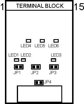
The TEV-IB1 contains three relays and three optically isolated inputs. Common, normally closed, and normally opened lines of each relay are available on the terminal block. Six status LEDs located on the board indicate the state of relays and opto-inputs.
The relays can switch loads of up to 24V/1A. This rating is for non-inductive loads only! For inductive loads, the maximum allowed current falls to about 200mA. Status LEDs 4~6 indicate the state of the relays. An LED will be ON when a corresponding relay is activated.
Each optically isolated input has a pair of (+) and (–) contacts with a 330Ω series resistor and a LED of the photo-couple between them. The input is activated at a differential voltage of around 4V, and can accept input voltages as high as 24V. Both (+) and (–) inputs are isolated from the rest of the system. Status LEDs 1~3 indicate the state of inputs. An LED will be ON when the current is flowing through a corresponding input and the input is "triggered."
You can use inputs 1~3 to connect to external sensors. Alternatively, inputs 1 and 2 can be used to attach a Wiegand or clock/data card reader. See below for details.
Related EM1000 I/O Lines
|
Pin #(1) |
EM1000 I/O line(2) |
Function |
|
1 |
TX |
Relay1(3) |
|
2 |
RTS |
Relay2(3) |
|
3 |
DTR |
Relay3(3) |
|
4 |
RX |
Input1(4) |
|
5 |
CTS |
Input2(4) |
|
6 |
DSR |
Input3(4) |
- Pin number on the TEV-IB1 connector.
- There are four ports, so lines are independent for each port. For example, "TX" means "TX0" for port 1, "TX1" for port 2, etc.
- Set GPIO line of the EM1000 LOW to activate the relay (do not forget to configure this line as an output).
- The GPIO line of the EM1000 will be LOW when the current is flowing through the input.
Terminal Block
|
Terminal # |
Function |
|
1 |
Relay1, common |
|
2 |
Relay1, normally closed |
|
3 |
Relay1, normally opened |
|
4 |
Relay2, common |
|
5 |
Relay2, normally closed |
|
6 |
Relay2, normally opened |
|
7 |
Relay3, common |
|
8 |
Relay3, normally closed |
|
9 |
Relay3, normally opened |
|
10 |
Input1, positive line (+) |
|
11 |
Input1, negative line (–) |
|
12 |
Input2, positive line (+) |
|
13 |
Input2, negative line (–) |
|
14 |
Input3, positive line (+) |
|
15 |
Input3, negative line (–) |
Connecting a Card Reader
The ability to handle a Wiegand or clock/data reader output is a unique feature of the serial ports of the EM1000. For more information, see the ser. object documentation.
When connecting a clock/data reader, attach the reader's DATA output to the positive line of input 1 of the TEV-IB1 board. Attach the CLOCK output to the positive line of the input 2. Combine the negative lines of inputs 1 and 2 together and connect them to the ground line of the reader. Leave JP4 jumper opened.
When connecting a Wiegand reader, attach the reader's W0 output to the positive line of the input 1 of the TEV-IB1 board. Attach the W1 output to the positive line of the input 2. Combine the negative lines of inputs 1 and 2 together and connect them to the ground line of the reader. Close the jumper JP4.
Most Wiegand readers have open-collector outputs, which means you may need to install pull-up resistors on their W0 and W1 outputs.
The function of JP4 is to combine the signals W0 and W1 — this is required for the EM1000's serial port operation in Wiegand mode.
Jumpers JP1~3 should be left open.