Multi-destination Mode
Multi-destination mode allows you to communicate with several Device Servers (and the serial devices behind them) through a singleVSP . To understand the usefulness of this feature consider the following example:
Example
Let's assume there is a multi-drop (RS485) network with several serial data terminals connected to it (see diagram below). The RS485 "bus" is attached to the PC's COM port via a 485-to-232 converter. An application software on the PC (App.) can address each terminal individually by sending a formatted command that contains a "node address" of the terminal. All terminals on the RS485 bus receive the command but only the one with a matching node address will respond to the command. This is a very common way of multi-drop communications. The PC acts as a "master" and the terminals act as "slaves".
.jpg)
The formatted command typically has a start character (STX, ASCII code 2 in this example), followed by the node address (transmitted, for example, as two ASCII characters representing the number, i.e. "01", "02", etc.). The address characters are followed by the command contents and some sort of end character (for example, CR, ASCII code 13):
STX |
Addr1 |
Addr2 |
Command contents |
CR |
Now let's suppose that you need to network-enable this system. The simplest way to do so would be to connect the RS485 bus to the DS, create a VSP on the PC and let the application software access the terminals through the VSP and the DS.
.jpg)
This will work, but only if the distance between the terminals is small. If the terminals are to be located far away from each other the RS485 network connecting them would have become very long thus defying the purpose of network-enabling this system! Much better solution would be to connect each terminal individually to its own DS (see figure below). This way there would be no RS485 network whatsoever.
.jpg)
The problem here is that each DS (and hence, each terminal) will now have its own IP-address and this means that a single VSP will have to switch between these IPs as needed (remember that on the original RS485 system the application software communicated with all terminals on the RS485 bus through a single COM port!).
The solution
The multi-destination mode of the VSP allows you to define several destination Device Servers and switch between these destinations basing on the outgoing data stream sent by the PC application. As explained above, the multi-drop RS485 system (almost) always has some form of node addressing and the VSP can be programmed to filter out this addressing information and automatically switch between the destinations.
The data in the outgoing data stream the VSP reacts to is divided into two portions:
| • | Prefix string- this is a fixed string that signals to the VSP that the actual node address will follow. Prefix can be any string of (almost) any length but it cannot be NULL (empty). Only one prefix string can be defined for each VSP. |
| • | Switch string- this is the data that immediately follows the prefix. The switch string is different for each destination listed in the destination table. Switch strings can also be of (almost) any length but cannot be NULL (empty). |
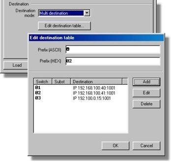
For the example used in this topic the prefix string is a single character with ASCII code 2 (STX) and the destination table looks like this:
Switch string |
Destination IP-address |
"01" |
192.168.100.40 |
"02" |
192.168.100.41 |
"03" |
192.190.0.15 |
Once the VSP detects the prefix string in the data stream sent by the application software it starts checking if the subsequent data will match one of the defined switch strings. When the match is detected the VSP closes current data connection (if any) and switches to the new destination, corresponding to the detected switch string.
Here is how this is reflected in the log of the Port Monitor :
12/18/03 10![]() 49 - COM3 (INFO): Port opened
49 - COM3 (INFO): Port opened
12/18/03 10![]() 04 - COM3 (INFO): Switching to 192.168.100.40:1001 ("01")...
04 - COM3 (INFO): Switching to 192.168.100.40:1001 ("01")...
12/18/03 10![]() 04 - COM3 (INFO): Established TCP connection with node 192.168.100.40:1001
04 - COM3 (INFO): Established TCP connection with node 192.168.100.40:1001
12/18/03 10![]() 15 - COM3 (INFO): TCP connection closed
15 - COM3 (INFO): TCP connection closed
12/18/03 10![]() 15 - COM3 (INFO): Switching to 192.168.100.41:1001 ("02")...
15 - COM3 (INFO): Switching to 192.168.100.41:1001 ("02")...
12/18/03 10![]() 15 - COM3 (INFO): Established TCP connection with node 192.168.100.41:1001
15 - COM3 (INFO): Established TCP connection with node 192.168.100.41:1001
Setting up the multi-destination VSP
To switch into the multi-destination mode and create the list of destinations select "multi-destination" from the destination mode drop-down box and click Edit destination table... button - Edit destination table dialog will open (shown on the screenshot below). The multi-destination mode is only available when the routing mode is "client" and when the connection mode is "on data". "Server/client" routing mode is not allowed because the VSP is supposed to act as a master and establish all connections by itself. "Connect immediately" mode is not allowed because the VSP needs to receive a switch string from the application in order to know which destination to connect to.

The prefix string is entered into the Prefix (ASCII) or Prefix (Hex)textboxes . These textboxes are synchronized with each other. Prefix (ASCII)texbox records the characters as you type them. For example, if you press <A> key this will be interpreted as ASCII character 'A'. The Prefix (Hex) texbox will reflect the ASCII HEX code of this character- 41. Typing "02" (ASCII code of the STX character) into the Prefix (Hex) textbox will cause the image of this character (smiley face) to appear in the Prefix (ASCII) textbox. Special characters, such as STX, can also be entered in the Prefix (ASCII) textbox using the <CTRL> key (<CTRL>+<B> for STX).
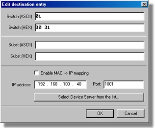
Available destinations are entered into the destination table - there are Add , Edit , and Delete buttons . Pressing Add or Editbutton opens the Edit destination entry dialog (see the screenshot below).

Switch (ASCII) and Switch (Hex) textboxes are used to enter the switch string for a particular destination.
Substs (ASCII) and Subst (Hex) textboxes provide additional functionality that haven't been mentioned yet. If the data is entered into those fields then the VSP will automatically substitute the switch string encountered in the data stream sent by the application with this substitution string.
For example, if the switch string is "01" and the substitution string is "00" then the following will happen (STX character is represented as J ):
Application-->VSP: *J *01ABC
VSP-->DS: J 00ABC
The destination portion of the Edit destination entry dialog is similar to that displayed in the VSP properties dialog in the single-destination mode. The destination DS can be defined by its IP-address or by its MAC-address, depending on whether the MAC-->IP mapping option is enabled or not. Destination port must match the one specified by the Port Number (DP) setting of the destination DS. Instead of typing in the data manually, you can press the Select Device Server from the list... button and choose the DS from the list.
How multi-destination errors are handled
| • | If, after the VSP is opened, the application starts sending "random" data without sending a prefix and a switch string first, or if the data after the prefix does not match any switch string, the VSP will be discarding this data until a valid prefix and switch are detected. |
| • | If, after a valid prefix and switch have already been detected and the VSP has established a connection with a certain destination DS, the VSP receives the prefix string that is not followed by any valid switch string, then the VSP will keep sending the data across the existing data connection. |