Connecting to Tibbo Devices
GA1000 Interface
The GA1000 communicates with Tibbo devices through an SPI interface. Your device will control the GA1000 through five general-purpose I/O (GPIO) lines:
- CS — SPI bus, chip select (active LOW).
- CLK — SPI bus, clock.
- DI — SPI bus, data in (must be connected to the DO line of the host).
- DO — SPI bus, data out (must be connected to the DI line of the host).
- RST — reset (active low). This line can be eliminated — see below for details.
 On all devices except the EM500, do not forget to configure the CS, CLK, DO, and RST lines as outputs. DI must be configured as input. The wln. object won't do this automatically. GPIO configuration is not necessary on the EM500, whose lines are bidirectional.
Providing Hardware Reset
The wln. object directly controls the CS, CLK, DI, and DO lines. However, your application must take care of the proper hardware reset for the GA1000. There are two methods for doing this:
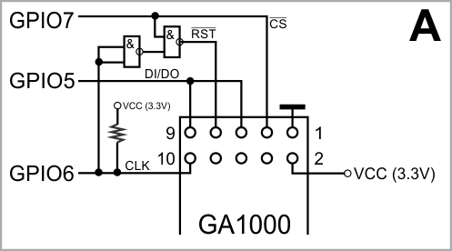
- Use a dedicated GPIO line to act as the RST line of the GA1000 interface (shown in diagram A below).
- Use two NAND gates to combine the CS and CLK signals and produce the reset signal for the GA1000 (shown in diagram B). This approach takes advantage of the fact that during SPI communications, the CLK line will never be LOW while the CS line is HIGH. The schematic diagram in figure B generates the reset when CS is HIGH and CLK is LOW. This way, you save one GPIO line of your programmable module.


Tibbo devices differ in whether the CS, CLK, DI, and DO lines are remappable. On the EM1000, EM1202, and EM1206, you can choose any set of GPIOs to control the GA1000. On the EM500, where remapping isn't provided, you just have to use "prescribed" GPIO lines.
Special Case — EM500
Diagram C shows the recommended way of connecting the GA1000 to the EM500 module. GPIO lines are a precious commodity on the EM500 — there are only eight of them available. You get away with using only three lines to control the GA1000 (compared with the standard five lines). One line is saved by producing the reset out of CS and CLK lines. The second line is saved because EM500's bidirectional GPIOs allow interconnecting the DI and DO lines. The EM500 does not allow the remapping of GA1000 lines, so the line assignment shown below cannot be changed.
Here is how to reset the GA1000 from the EM500:
- Set GPIO7 (CS) HIGH
- Set GPIO6 (CLK) LOW
- Set GPIO5 (CLK) HIGH