Power, Reset, PLL Control, MD Button, and Mode Lines
Power
The EM1001 consumes around 250mA @ 3.3V of current (PLL on, 100BaseT mode, all onboard LEDs on).
There are two ways to power the EM1001.
Powering Through the Regulator
The onboard switching regulator has an 8V~20V input range and delivers enough current to power the EM1001 and the WA2000 Wi-Fi add-on module, as well as external loads with up to 1A of combined current.
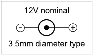
To use the regulator, connect the power source to the power jack or GND and VIN pins. The power jack and GND/VIN are wired in parallel, with no diodes or any other circuitry between them.
The regulator has a single diode in front of it. The diode will protect the regulator if the power is accidentally connected in reverse.
External loads can be powered through the 3.3V pin. When the board is powered through the regulator, this pin serves as a power output. Up to 1A of current is available with the WA2000 installed, 1.3A available if the WA2000 is not installed.
Using direct 3.3V power
It is also possible to power the EM1001 through the GND and 3.3V lines. In this case, the 3.3V pin serves as a power input and the regulator is bypassed. The 3.3V power source should be regulated to at least ±10%.
Board Reset
A proper external reset is not required. The EM1001 has a reliable power-on reset circuit with brown-out detection. You can optionally connect a reset button or some other reset-generating circuit to the RST pin. This will allow you to generate "external" resets. The RST line has active HIGH polarity. If you are not using the RST line, you can leave it unconnected.
PLL
The main clock frequency of the EM1001 is generated by the 11.0592MHz crystal connected to the onboard PLL circuit. When the PLL is off, the EM1001 is clocked at 11.0592MHz. When the PLL is on, the main clock is eight times higher — 88.4736MHz. Naturally, with PLL turned on the EM1001 works eight times faster and consumes more current (250mA @ 3.3V with PLL on vs. 130mA with PLL off). The main clock frequency also affects the baudrates of serial ports when in the UART mode, as well as the frequency produced by the square wave generator.
The PLL cannot be switched off and on while the EM1001 is running. This is because when the PLL mode changes, its output needs some time to stabilize. For this reason, the PLL mode of the EM1001 can only be changed on reset. A special internal delay circuit will hold the EM1001 in reset while the PLL frequency stabilizes.
The state of the PM pin at power-up or after the external reset (i.e., a reset pulse on the RST line) defines whether the EM1001 will run with PLL on or off. To have the PLL on, leave the PM pin unconnected. To disable PLL and run at lower clock frequency, ground the PM pin prior to turning on the power or resetting the board.
Your Tibbo BASIC/C application can also change the PLL mode programmatically. The application can check the current PLL mode through the sys. object. If the PLL mode needs to be changed, the application must set the desired new mode and then perform an internal reset (again, through the sys. object). The internal reset is identical to the power-on or external reset with one crucial difference: The PLL mode is set based on the mode requested by the application, while the PM line state is disregarded.
MD Button and Line
The function of the MD button/line is described in Setup (MD) Button (Line). The EM1001 has both the button and the MD line. The button is wired in parallel with the MD line. Use an open collector circuit to control the MD line, as pressing the MD button short-circuits the line onto the GND.